(*) The Datasheet can be accessed from the Mouser Electronics website at: http://www.mouser.com/pdfdocs/20005791a.pdf
In addition to the features indicated the MCP6411 has improved EMI protection, which is important in applications subject to this type of problem.
The MCP6411 comes in SC70-5 and SOT-23 enclosures being built with an advanced CMOS process.
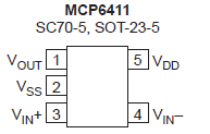
In figure 1 we have the wrapping and pin identification of this component.
The main electrical characteristics of this component are:
Vdd - Vss: 6.5 V (max)
Current on the analog input pins: +/- 2 mA (max)
Output pins current: 2 mA (max)
Source rejection: 75 dB (min)
CMMRR: 65 dB (min)
Signal gain without feedback: 95 dB (min)
Power: 1.72 to 5.5 V
Correne quiescent: 45 uA (tip)
GBWP: 1 MHz
Here are some practical application circuits for this component.
Carbon Monoxide Sensor
This application aims to detect the presence of carbon monoxide (CO) gas in an environment, which is extremely dangerous for the presence of humans.
Sensing devices of this gas are typically portable (battery powered) types emitting an audible sound when hazardous gas levels are detected.
In figure 2 we have a typical circuit suggested by Microchip using the MCP6411 operational amplifier.
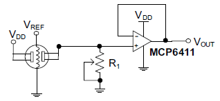
Figure 2 - carbon monoxide detector
The sensor is of the conventional type used in these applications. The purpose of potentiometer R1 is to make the calibration according to the environment.
Pressure Sensor
In figure 3 we have another application for the MCP6411. It is a circuit for a pressure bridge sensor.
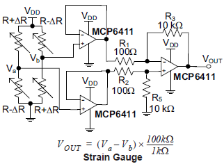
Figure 3 - Pressure sensor
In this application they are used, connected in order to function as buffers in order to prevent the bridge from being charged. The resistors R1, R2, R3 and R5 must have a very close tolerance for the lowest CMRR to be achieved.
Battery Current Sensing
The next application for the MCP6411 suggested by Microchip is a battery current sensor, shown in figure 4.
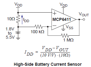
Figure 4 - battery current sensor
As we can see, it is a high-side circuit (positive side or high side) that is intercalado between the positive of the power (battery) and the circuit fed.
The formula next to the diagram allows to calculate the output current as a function of the input current.
In Microchip's application note we find reference to several other applications notes with important content for the project with operational amplifiers.
